Case Study:
Tuning a 2-way or Bi-amp System
My obessesion for the Clair Brothers 12am started shorted after walking up to one in the late 90's and thinking, "Now this is what a monitor should sound like"
It took ten years to finally say that I owned one and once you have one, you need more.
Everyone has the story of that special piece of gear that they got for cheap. With the economy taking a slight turn eBay has been an excellent source to find something that might have been originally out your price range. Before eBay we traded gear amongst ourselves and found the occasional piece through a pawn Shop or corkboard at the local music broker. With technology advancing those that have the money to move forward do and tend to dump their gear to the highest bidder regardless if it reaches the fair market value. This attitude has allowed me to maintain the quality inventory of a mid level sound company while bringing in the funds of a weekend warrior. Thus the story of my Clair Brothers 12am monitor wedge. I got it for so cheap that I felt bad for the AV Liquidation Company that sold it to me because they didn't know what they had on their shelves. In all fairness I have spent thousands of dollars buying gear from them over the last few years. They've made plenty off of me in the course of our history.
The need to own such a piece of gear comes from one long-term client, who too, loves the CBA 12am monitor. So when I told him that it was his new monitor he got overly excited. I explained to him that it was listed as an “unknown manufacturer” and that the description indicated that they the high frequency driver didn't work and the JBL 2206 12" driver was fully functional. Ok, so at very least I might have to replace a $200 diaphragm for a JBL 2450j. If I got it for less than $500 dollars I was still way ahead. The auction ran during the week that spanned Christmas to New Year and to my advantage no one was just surfing. Perusing the web would have been the only way you would have found this thing since there was not a proper description for search engines. So I bought my $2500 monitor uncontested for $88 and approximately 3 pennies worth of solder to repair the loose connection on the 2450 high frequency driver
The next step was to see what I had technically speaking and then choose an amplifier and crossover for the beast. I already had a BSS FDS336 omnidrive lying around from a previous bi-amp monitor rack and some extraneous amplifiers. The specs for the JBL drivers suggested that I needed to put 600 watts behind the 12" 2206 and around 150 watts should be applied to the 2450j. After realizing that I just didn't have anything that I could use I started the online search for something light and powerful. I came across the QSC PL1.6HVX- a short-lived product that didn't take off so there aren't too many around. As luck would continue on this project I was able to find one used on eBay from a sound company that no longer needed it. I paid around $600 for it but it gave me almost the exact wattage specification that I needed in one amplifer. Channel 1 was designed for the low frequency driver and channel 2 was designed for the high frequency driver in the sense that it's output was two-thirds of channel 1. The amplifier came with an internal circuit board with filtering so you can use it without an external crossover.
Since I had the Omnidrive I decided to give the 12am what it needed in terms of proper driver eq and phase alignment. Here's where this story begins....
Most audio guys can tell you about Polarity and will continue to try to describe Phase as Polarity. This works for about one sentence and by the second sentence of trying this description you would be confused. You can know very little about that mysterious thing called Phase and perform the task that I'm going to be demonstrating in this tutorial, I know very little about the subject and after email exchanges with the guys such as Bob "606" McCarthy that have written books on the subject I'm barely further along.
For this tutorial we are going to be looking two different crossover elements: the common electronic crossover and the more elusive acoustical crossover. The electronic crossover is a fairly simple concept that it familiar to most people who have ever set-up a 2 or 3 system. For each frequency range you would a pass band dedicated to cover that range. The pass band is defined with parameters such as gain, high pass filters (low cut), low pass filters (hi cut), and the slope of the filters that determines the interaction between the two pass bands. The electrical designer defines these slopes and the number of dB's per octave the signal trails off. For instance a 12db slope would mean that the signal reduces at a rate of 12 dB's over the course one octave.
For the purpose of setting up the 12am I only needed to find out JBL's specifications for frequency response of the two drivers I was ready to start. The specs indicated that the 12" driver would re-produce 50Hz to 4kHz with no trouble and the 2450 HF driver was good starting around 500 Hz on up to 16kHz. I had a lot of room to fluctuate with my cross over point so I decided to go for 1kHz so I could use the most of the highly efficient high frequency driver as I could. I choose to go with a LR24 slope between the two drivers to keep them tight. Since the monitor doesn't need to reproduce sub or ultra sonic frequencies I put safeties of 40Hz and 16kHz. I used BW 6 filters on the upper and lower echelon because the Omnidrive uses one filter for those, but an Linkwitz-Riley 24 filter requires 2 filters per pass band in the Omnidrive. That's equivalent to 2 eq filters that I could be using elsewhere, if I needed them.
Once the Omnidrive was set-up with the correct crossover points it was time to get started with the measurements. The first step was to get the frequency response of each of the drivers in their raw format, but with the crossover point that I had chosen.
Tip: you can right click and save any of the images to view than at full!
JBL 2206 12" Low Frequency Driver:
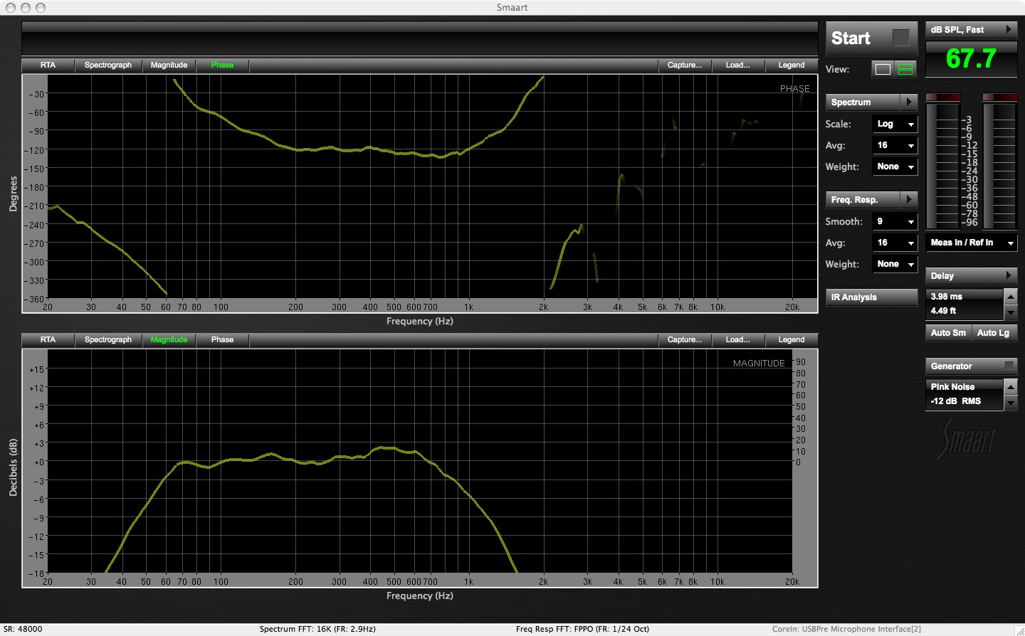
JBL 2450j 2" High Frequency Driver
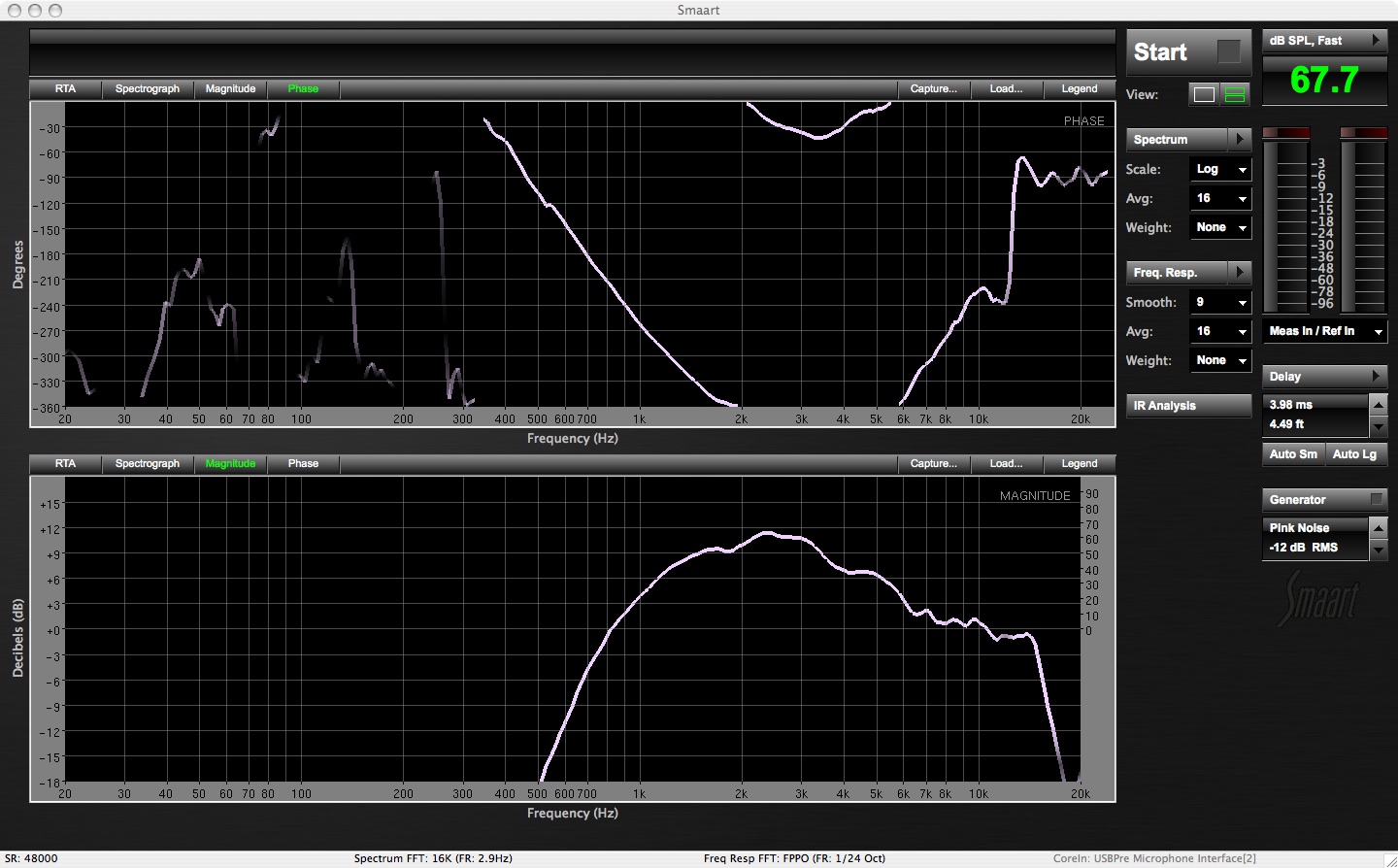
Once I began to see what I was up against it was time to get to work on the HF driver getting it EQ'd to fit the needs of a monitor wedge. Monitor wedges need to be clear at the intelligibility frequencies, but not this clear. The over abundance of in the high mid range would make the monitor sound a little harsh or edgy. I'm look for a nice warm sound, something not always associated with JBL compression drivers. It may be a little hard to see but the peak of the curve is centered on 2.5kHz +9dB and it would take large notches from 1.25 kHz through 3.15kHz on a graphic eq to flatten this driver out. Since we are using the Omnidrive we can utilize the parametric eq and clear this main hump up with just one or two parametric eq's. I started with a frequency point of 2.29kHz and lowered by 9dB but spread the Q or width out to cover almost an entire octave (.950) this was worth more than three 1/3 octave filters.
Now that the main hump was gone I used a few choice filters to flatten out the 3 kHz to 5kHz range. (It should be noted that I had 100% data coherence in this area so I knew that it was true bumps in the spectrum and not a by product of comb filtering.) I choose two points at 3.03kHz -2.5dB with a Q=.30 and 4.92kHz -3dB with a Q=.30. Finally I needed to work on the lower range of the driver to remove some of the over coverage lower section. 1.31kHz down 3dB with a width of .30 changed the bottom slope for me to get me back to my defined parameters.
JBL 2450j High Frequency Driver Comparison Raw (White) vs EQ's (Blue)
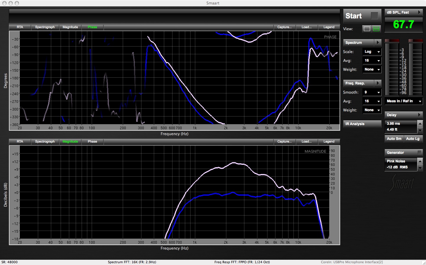
Now that I had the driver that JBL had wished they had made I just needed to reduce the gain by -2dB to find myself averaging around +/- 2dB of the OdB line. It was time to move on to the 12" 2206 driver and get it eq's for action. Although the driver looked good enough for action I had to make some decision based on the known use of this monitor. I already knew that it had to produce over 100dB SPL of Acoustic Guitar and knew where the problem frequencies were. So with my raw trace pulled back up I begin to eq out the 482Hz (-3dB @ .30) the driver needed and then the 162Hz and 637Hz (both 2dB @ .30) to increase my gain before feedback. The final step in eq'ing the 2206 driver was to remove 3dB of 1.14kHz. Just because it's above the crossover point doesn't mean you can ignore it. It's a vital part of the final frequency and phase response
With the pink noise muted I was then able to look at the two individual pass bands and get an idea of where I stood with my eq choices.
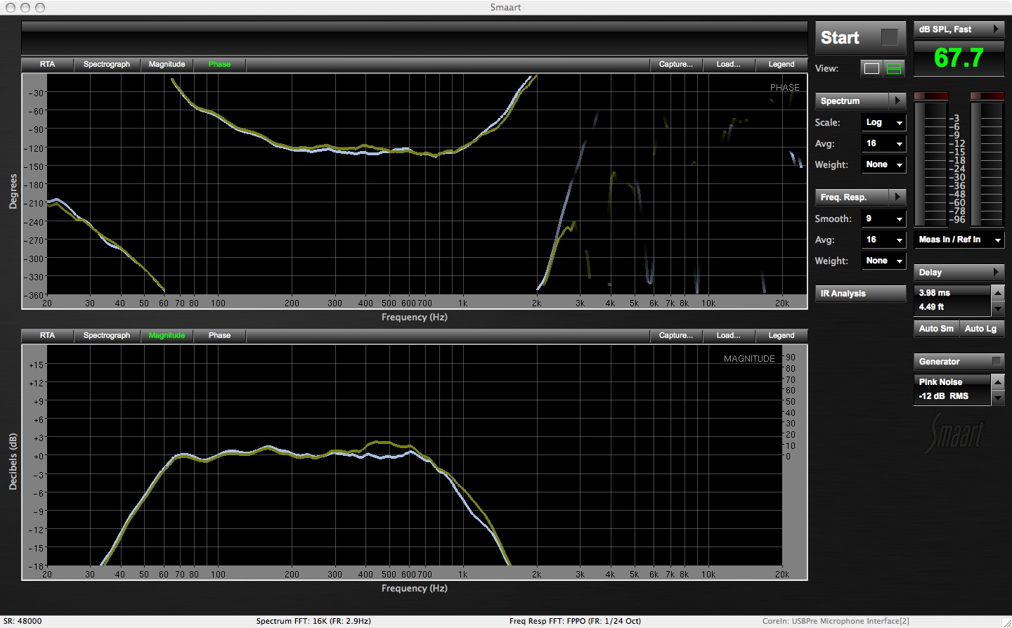
JBL 2206 LF Driver (Grey) and 2450j HF Driver (Blue) after EQ:
 & 2450.jpg)
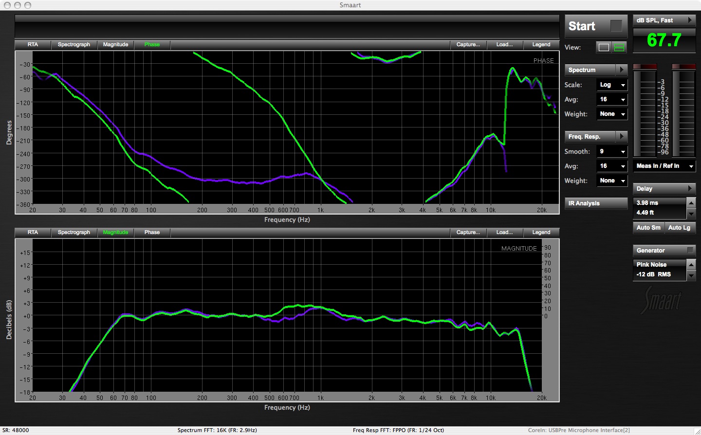
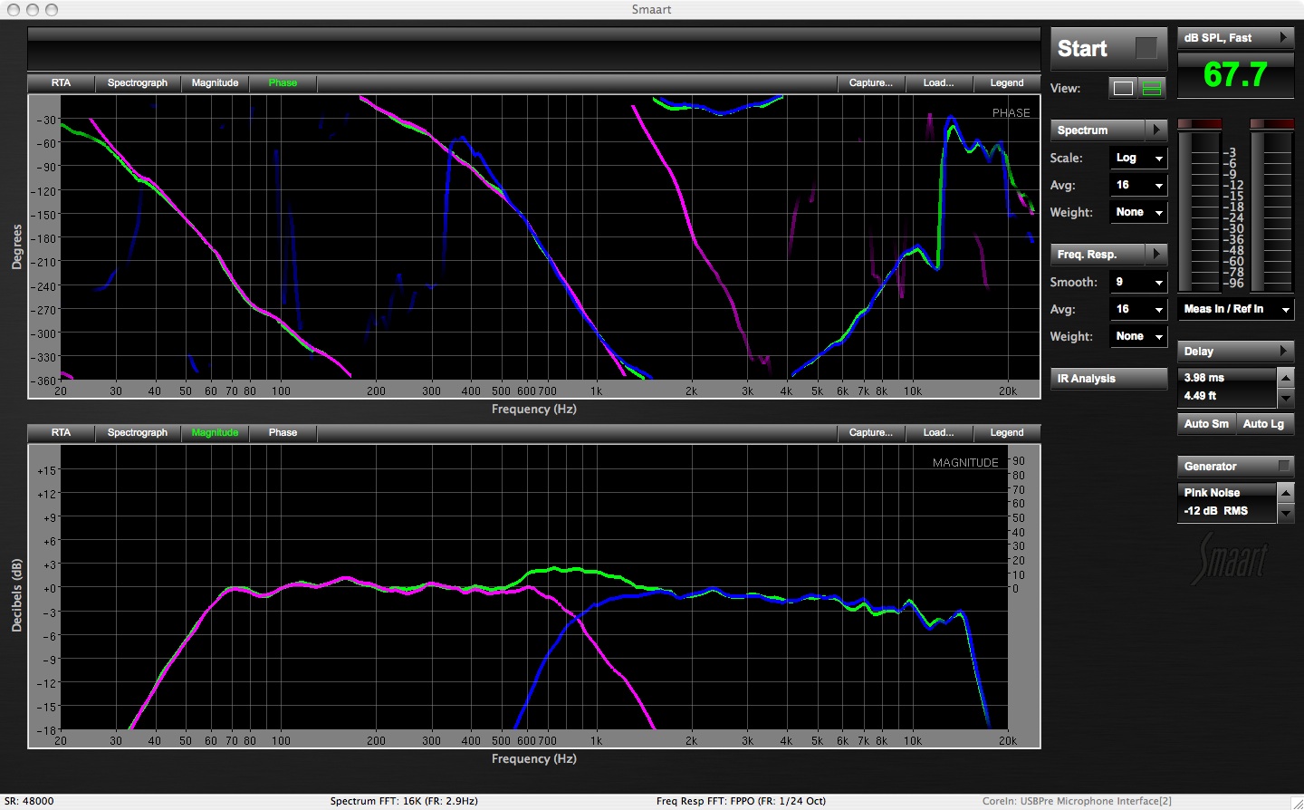
The next step begins the work on the acoustical crossover of the two drivers. This is the area where the independent drivers converge in the free field outside of the cabinet and give is the audio that we would hope and expect to hear. This is where just a little and I stress a little knowledge of phase can help you gain valuable prizes such as a free headroom and not burning the voice coils in your speakers. At this point it's all about time. Time=Frequency=Phase is a simple way to put it when thinking about how they all work together. We know that the lower the frequency the more time is takes for the wavelength to go from Positive Polarity to Negative Polarity by drawing out a simple sine wave. Inversely a higher frequency takes less time to follow the same polarity path.
When it comes to phase of a driver we can change the phase response with time. We can't move forward in time (yet!) but we can go backwards with the use of delay on the pass band. A shift in the polarity (+ or -) of a driver can also shift the phase favorably. Looking at the above image you can see what looks like two "U" shaped patterns in the upper phase window. We immediately see that at the crossover point (1kHz) the difference between the 2 traces is just slightly more than 180 degrees out of phase. We already know that when you take two identical signals and put them 180 degrees out of phase are you going to begin to hear cancellations. A cancellation can't be fixed with an eq because it's just gone.
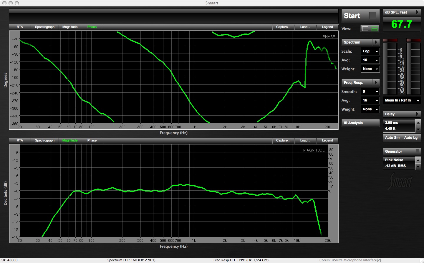
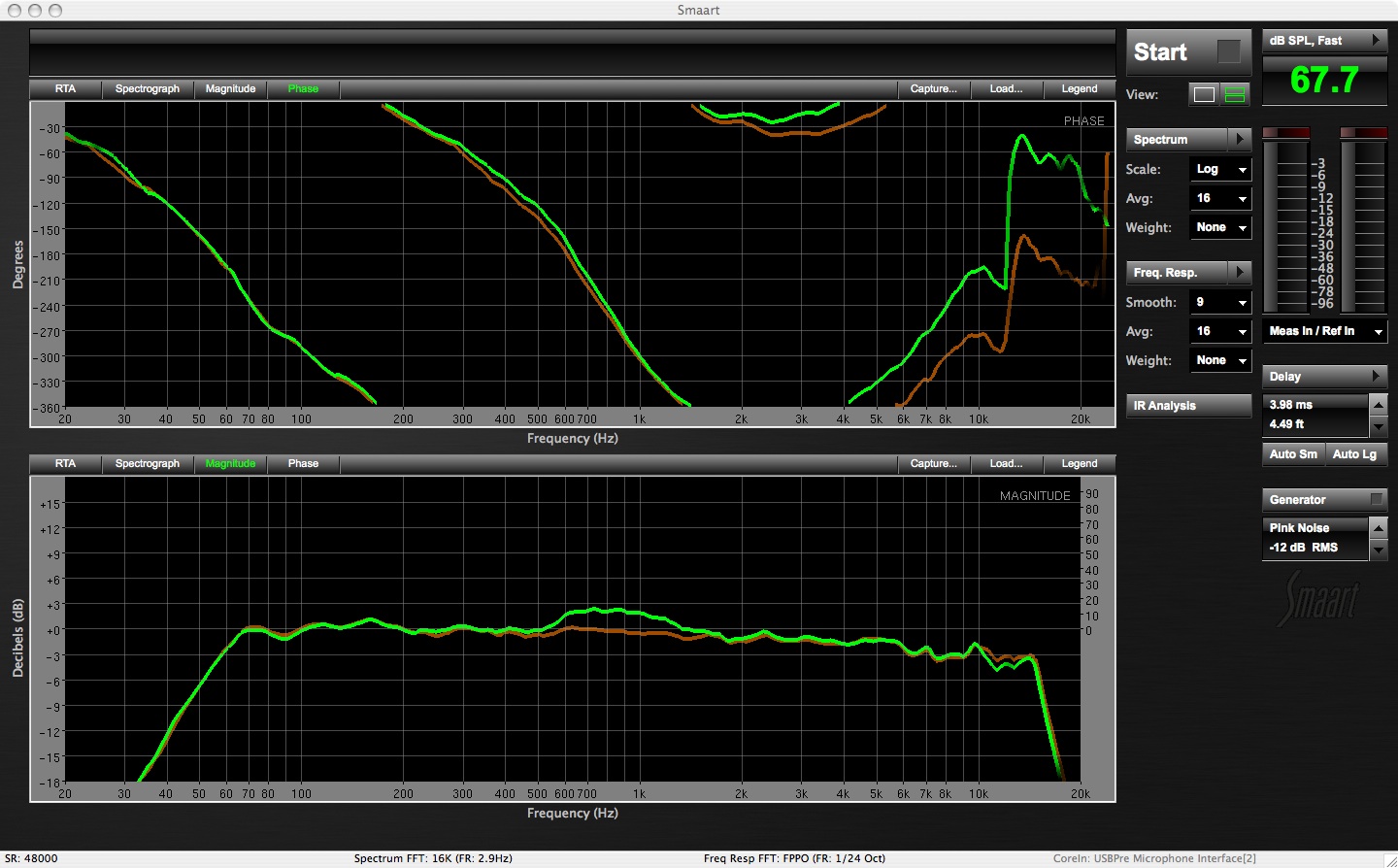
In order to correct the phase relationship between the two drivers we are going to use a mixture of polarity reverse and delay. You could do the whole fix with just delay, but the polarity reverse is going to give you a jump backwards in time that enables you to use less delay. By immediately reversing the polarity on the low frequency driver we are able to get us most of the way there: 180 degrees worth of the distance. However, we are more than 180 degrees out so we need to begin applying delay to the LF output until we've layered the phase of the crossover points on top of each other- thus putting them in true relative phase. The next image shows the result of reversing the polarity on the LF driver and adding what amounted to be 1ms of delay. (Note: I have other 2 way systems that needed less delay because of internal driver placement or initial phase response of the driver).
The final result is the lines that represent the phase layered on top of each other in the acoustic crossover.
Phase adjusted within the crossover region:
 & 2450.jpg)
By referring back up to the image that shows the LF, HF and Full we see a 2.5dB bump in the crossover area., We can take care of that two different ways with the use of EQ. The textbook procedure would be to go back a few steps and re-eq the upper LF and lower HF driver areas to get a correct curve. If there is any question about what the shape should be you could always measure and capture the crossover itself and give you some target curves to compare to as you are you eq'ing the individual drivers. I'm going to cheat a little because my Omnidrive will let me.
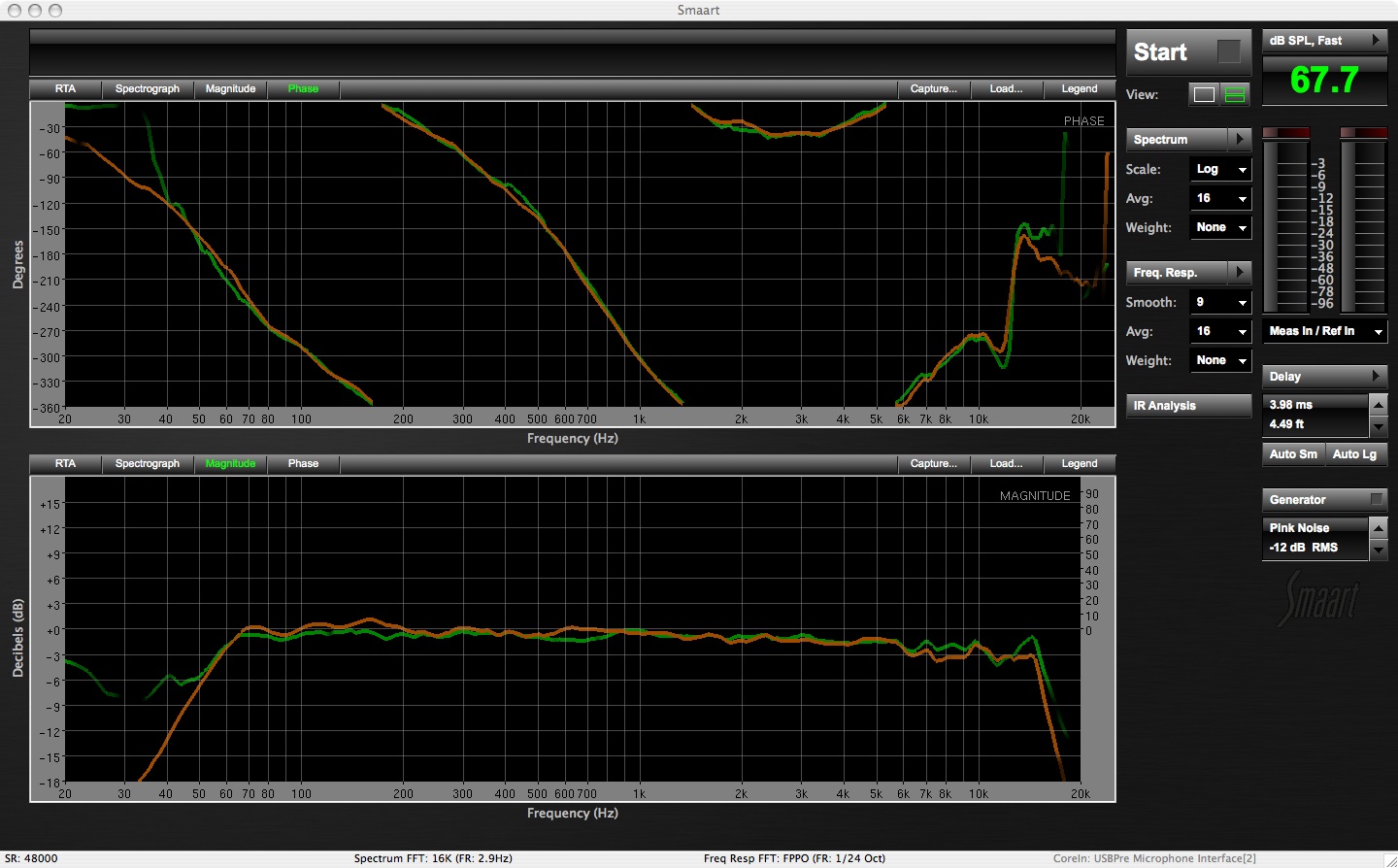
Without backtracking I have EQ on both the inputs and the outputs of the processor that I can utilize in the process. Some processors such as Driveracks have parametric eq’s on the outputs, but are limited to graphic eq's on the inputs. To flatten out the hump or what I've heard system analysts call "free head room" I am going to use a parametric on the inputs of the Omnidrive and EQ the incoming signal before it hits the crossover network. By reducing 840Hz by -2.5 dB what worked out to be a full octave we are back to flat.
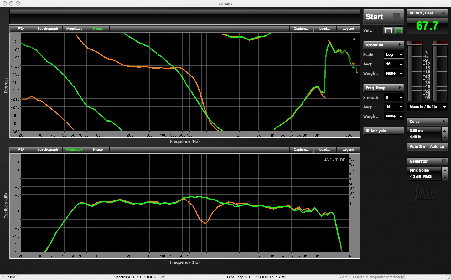
Input EQ applied for almost final adjustment (brown trace)
** I say almost final because the last step is to put it in action and see how it reacts to an open microphone the resonance of an acoustic guitar!
So why is phase alignment step important? What would happen if we just eq'd the two bands and called it good? Let's look at a few scenarios and see what happens if we remove the phase alignment elements from the big picture. We'll start by comparing the almost final trace with a version with just delay or polarity reversal. We can see compare the phase response which has a direct effect on the frequency response. At this point you cannot eq that dip back into the system because it's gone. Trying to eq it back will force the drivers to reproduce it but it will continually cancel itself out as it leave the speaker cabinet.
Next we'll look at the same scenario except we add the delay but not flip the polarity on LF driver. The result is a fairly good, usable frequency response, but a shift in phase that occurs in the upper end of the LF driver.